




Common Twin-Screw Extrusion Defects and How to Troubleshoot Them
A twin-screw extrusion defect is rarely caused by one temperature setting or one machine component alone. Most defects emerge when material behavior, feed consistency, screw configuration, thermal history, pressure development, and downstream conditions fall out of balance. The fastest way to reduce scrap is therefore not to change several settings at once, but to identify whether the fault begins at the feeder, inside the process section, at the die, or after the melt exits the extruder.
For compounders handling filled, reinforced, recycled, flame-retardant, or moisture-sensitive polymers, the same visible defect can have very different root causes. Black specks may indicate polymer degradation, contamination, or stagnant material in a low-flow area. Voids may result from inadequate drying, poor vacuum efficiency, entrained air, or decomposition of a reactive additive. A structured diagnostic method is more reliable than treating every problem as a temperature issue.
Start with the defect pattern, not the machine setting
Before changing operating conditions, determine when and where the defect appears. A defect that occurs immediately after startup points to residual material, poor cleaning, an incorrect initial temperature profile, or instability in the feed system. A defect that develops after stable running more often involves screen-pack loading, die buildup, feeder bridging, thermal drift, wear, or changes in incoming material.
The form of the defect also matters. Random defects across a production run suggest variable raw material, feeding fluctuation, contamination, or intermittent venting problems. Repeating defects at a regular interval can indicate screw damage, pulsation from a feeder or melt pump, rotating die contamination, or a mechanical issue in downstream handling. Defects concentrated near one side of a sheet, strand, or profile usually require attention to die flow distribution, die temperature, cooling symmetry, or localized contamination.
A useful troubleshooting record should capture the resin grade and lot, moisture condition, additive package, feeder rates, screw speed, torque, melt pressure, melt temperature, vacuum level where applicable, die temperature, and the time when the defect began. Without this baseline, production teams may correct a symptom temporarily while losing the evidence needed to find the cause.
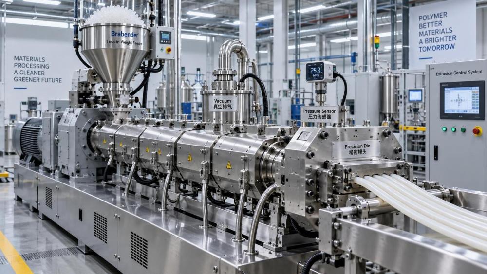
Poor dispersion and visible agglomerates
Undispersed pigment, mineral filler clusters, glass-fiber bundles, flame-retardant particles, elastomer gels, or additive specks are among the most common quality problems in compounding. They can affect appearance, mechanical consistency, electrical behavior, film performance, and downstream molding reliability. In severe cases, hard agglomerates can block fine screens, damage dies, or create weak points in finished parts.
Poor dispersion is often blamed on insufficient screw speed, but increasing speed alone may make the problem worse. Higher screw speed raises shear and can improve distributive and dispersive mixing, yet it also reduces residence time and may increase melt temperature. With heat-sensitive polymers or additives, this can produce degradation before the dispersion problem is solved.
Check the raw material before modifying the screw program. Fine powders may form stable agglomerates during storage or transport, while hygroscopic materials can cake after moisture uptake. Filler particle-size distribution, surface treatment, bulk density, and feeding behavior all influence whether the material can enter the melt uniformly. A feeder that delivers an apparently correct average rate but pulses in short cycles can create repeated zones of poor mixing.
Within the extruder, the location and intensity of mixing elements must match the material. If a solid filler is introduced too late, the polymer may not have enough melt development or mixing length to wet and disperse it. If high-shear kneading blocks are installed too early, before the base resin is fully molten, they may compact powder or overload the screw rather than improve dispersion. The process needs enough melt seal and pressure to transmit shear, but not so much restriction that material overheats or residence time becomes excessive.
Corrective action should proceed in sequence: stabilize feeder output; confirm dry-blend quality and powder handling; verify that the polymer is adequately molten at the addition point; then evaluate screw elements, barrel fill, and throughput. Microscopic inspection or ash-content checks of samples taken along the process can help distinguish a dispersion problem from an inaccurate formulation feed.
Feeding instability, output variation, and surging
Surging appears as fluctuating throughput, melt pressure, strand diameter, sheet thickness, pellet size, or motor load. It is a process-stability issue rather than a simple capacity issue. When mass flow changes at the inlet, every downstream control loop receives an unstable signal; pressure and die flow can then oscillate even if barrel temperatures remain steady.
Loss-in-weight feeders should be evaluated for refill disturbances, bridging, rat-holing, screw wear, hopper geometry, vibration, and material bulk-density variation. Low-bulk-density powders, fibers, regrind, flakes, and blends with separated components are particularly difficult to dose consistently. A feeder can be mechanically functional while still delivering variable composition because different ingredients segregate inside the hopper.
Air entrainment is another overlooked source of instability. Light powders may carry large volumes of air into the feed section, reducing effective fill and causing pressure fluctuations. Excessive side-feeder speed can also force material into the barrel unevenly, especially where the melt seal is weak or the side-feed zone is not sufficiently vented.
Inside the extruder, unstable pressure may reflect a partially blocked screen, die-lip buildup, inconsistent melt-pump operation, or inadequate melt sealing before a vacuum vent. A sudden rise in pressure accompanied by falling output often suggests restriction downstream of the screws. Falling pressure and unstable torque may instead indicate feed starvation, insufficient barrel fill, or material escaping through a vent opening.
Do not attempt to suppress surging by raising barrel temperatures indiscriminately. Lower viscosity may temporarily reduce pressure fluctuation, but it can conceal the actual feed or restriction problem and create additional risks of degradation, die drool, or poor pelletizing behavior.
Voids, bubbles, and porous strands
Voids are evidence that gas, vapor, or volatile compounds remain in the melt when it leaves the die. In hygroscopic polymers such as polyamide, PET, PBT, TPU, PC, and certain recycled materials, residual moisture can hydrolyze polymer chains during processing. The result may be bubbles, reduced molecular weight, reduced mechanical performance, and unstable viscosity—not merely a cosmetic defect.
The first question is whether the gas originates from the raw material or from the process. Verify drying conditions against the material supplier’s processing guidance, including drying temperature, dwell time, dew point capability, and protected transfer from dryer to hopper. A properly dried resin can reabsorb moisture if it remains exposed in an open feed system, particularly in humid production environments.
For filled or recycled formulations, moisture may come from fillers, regrind, packaging residue, paper labels, organic contamination, or absorbed water in porous materials. Volatile residues can also originate from residual monomers, solvents, processing oils, decomposition products, or incompatible additives. These sources require a material and formulation review rather than a dryer adjustment alone.
Where vacuum degassing is used, inspect the vent opening, condenser, vacuum line, filters, seals, and pump condition. A low indicated vacuum does not guarantee effective devolatilization if the vent is flooded by melt, the screw design does not create a stable upstream melt seal, or the material has insufficient surface renewal in the vent zone. Conversely, an overly aggressive vent arrangement can pull fines from the barrel, contaminate the vacuum system, and alter formulation balance.
To distinguish moisture from poor degassing, compare a controlled, freshly dried sample with normal production material while holding the rest of the process stable. If defects persist with verified dry material, examine vacuum function, melt temperature, residence time, and potential chemical decomposition. If bubbles disappear but melt strength remains low, the material may already have undergone hydrolytic or thermal degradation before extrusion.
Discoloration, black specks, and burnt material
Yellowing, dark streaks, black specks, and burnt odor indicate that the material has encountered excessive thermal or shear history, contamination, or stagnant zones. The location and timing of discoloration are important. A broad color shift across the entire output is more consistent with overall overheating or a raw-material change. Isolated black specks often point to degraded residues being released intermittently from dead spots in the feed section, screw splines, vent ports, adapters, screen changers, melt pumps, or die corners.
Actual melt temperature deserves more attention than displayed barrel-zone temperatures. Shear heating from restrictive screw elements, high screw speed, high viscosity, or excessive back pressure can raise melt temperature well above the setpoints. A thermocouple in the barrel wall cannot fully represent the melt’s thermal history.
Material degradation can also be caused by long residence time at low throughput. This is common when a line is operated far below its intended output, when restrictive screens create excessive hold-up, or when screw design produces stagnant material pockets. Heat-sensitive polymers, certain flame-retardant systems, recycled resins, and formulations containing reactive additives have narrower processing windows and require particular control of residence time.
Cleaning should focus on the full melt path, not only the screws. If black specks recur after purging, inspect screen packs, breaker plates, adapters, melt-pump cavities, die manifolds, and vent areas. A purge compound may remove loosely retained resin but will not correct worn components, damaged chrome surfaces, improperly seated screens, or geometric dead zones. When changing from a high-temperature resin to a lower-temperature material, incomplete removal of the prior polymer can also create specks and gels long after startup.
Gels, unmelted particles, and inconsistent melt quality
Gels are not always the same defect. In some systems, they are crosslinked or oxidized polymer fragments that resist melting. In others, they are unmelted resin particles, incompatible recycled-polymer domains, elastomer clusters, or contamination. Their behavior under heat and filtration helps identify the likely cause.
Unmelted particles suggest inadequate melting capacity, excessive throughput, a feed-zone temperature issue, poor raw-material contact with the screw, or an unsuitable screw configuration. Raising downstream temperatures may not help if the material is leaving the feed zone poorly conveyed or reaches the melting section without adequate compression and mixing. Some semicrystalline resins also need a temperature profile that supports progressive melting rather than abrupt overheating.
Crosslinked gels and oxidized particles are more closely associated with excessive thermal exposure, oxygen contact, contaminated regrind, or degraded hold-up material. They may pass through the extruder unchanged and become visible only in films, sheets, fibers, or thin molded parts. Fine filtration can reduce the visible defect, but it does not remove the underlying cause and may add pressure, shear, and further degradation.
For recycled feedstocks, gel control depends heavily on input consistency. Mixed polymer streams, incompatible labels, residual adhesives, paper, wood, metal fines, and degraded fractions can produce defects that screw speed cannot solve. Incoming inspection, pre-filtration, metal detection, washing quality, and lot segregation may be more effective than additional mixing intensity.
High torque, high pressure, and unexpected temperature rise
High torque indicates that the screws are encountering more resistance than expected. The immediate risks are overload trips, accelerated wear, inconsistent mixing, and thermal damage from shear. High torque with high melt pressure often indicates a restriction: blocked screens, a restrictive die, excessive kneading intensity, low barrel temperatures, or a formulation with higher-than-expected viscosity or filler loading.
High torque with relatively low pressure points in a different direction. It may reflect poor solids conveying, bridging, excessive friction in a partially melted zone, mechanical contact, or a screw configuration that is overfilling a section without developing stable downstream pressure. Changes in raw-material particle form can be significant: pellets, powder, flakes, and regrind of the same nominal polymer do not fill and convey identically.
When torque rises gradually over a run, inspect for screen loading, die buildup, material accumulation in vent zones, or changing feed moisture. A sudden step change may indicate an incorrect feeder setpoint, foreign material, a mechanical malfunction, or an abrupt change in resin viscosity. The response should be based on the operating trend, not the final alarm value alone.
Die lines, surface roughness, and dimensional instability
Surface defects after the die are often attributed to die temperature, but the melt arriving at the die may already be nonuniform. Die lines can result from contamination, damaged die surfaces, incomplete mixing, screen breakthrough, or unstable flow distribution. Roughness can indicate poor melt homogeneity, filler agglomeration, moisture, excessive drawdown, or cooling conditions that freeze surface irregularities before they relax.
Dimensional variation in strands, profiles, sheet, or film should be separated into melt-flow variation and downstream handling variation. If melt pressure and extruder output are stable while dimensions fluctuate, examine haul-off speed, cooling-water temperature, calibrator conditions, air-ring balance, nip pressure, pelletizer synchronization, or winding tension. If dimensions track pressure movement, return to feeding, filtration, die restriction, and melt-pump stability.
For sheet and film applications, localized thickness variation may require die-lip adjustment, but mechanical adjustment should not be the first response if the profile changes over time. A drifting profile often reflects temperature imbalance, contamination buildup, unstable throughput, or uneven cooling rather than a permanent die geometry issue.
Control the process as a connected system
Twin-screw extrusion troubleshooting becomes more effective when defects are linked to measurable process signals. Feeder mass-flow trends, torque, specific energy, melt pressure, melt temperature, vacuum performance, and downstream dimensions should be reviewed together. A single reading rarely identifies the root cause; the relationship between readings does.
Changes should be deliberate and isolated. Adjusting feed rate, screw speed, barrel temperatures, vacuum, and die settings simultaneously may restore acceptable output, but it prevents reliable learning and makes recurrence more likely. A stable operating window should define not only setpoints but acceptable variation in material preparation, feeder behavior, pressure, torque, and melt temperature.
The practical answer to what are the common defects in twin-screw extrusion and how to troubleshoot them is therefore not a universal list of settings. Poor dispersion, surging, voids, discoloration, gels, overload, and surface defects all require the same discipline: confirm the material condition, locate the stage where instability begins, interpret process variables as a system, and correct the cause before compensating at the die or downstream equipment. That approach protects material performance as well as output consistency.
Have questions about this sector analysis, or seeking best practices specific to your niche? Drop us a line below and let the senior consultants at APIM assist you.
We respect your privacy. Your information is strictly confidential.
Related News
- 00
0000-00
Do polyolefin hot melt adhesives bond well to polyethylene? - 00
0000-00
Korean Study Finds PLA Barely Degrades in Landfill After 320 Days - 00
0000-00
How to assess batch consistency from a thermal potting compounds supplier - 00
0000-00
How much weight can carbon fiber reinforced plastics save in cars? - 00
0000-00
Switching from PS to ABS Sheet Extrusion: Equipment Checks