




How conductive polymer compounds affect EMI shielding performance
Conductive polymer compounds are moving from niche materials into mainstream EMI control strategies, especially in electronics, automotive electronics, industrial automation, telecom hardware, and compact medical and sensing devices. For technical evaluators, the key issue is not whether a compound is “conductive” in a general sense. The real question is how formulation and processing translate into shielding effectiveness across the target frequency range, part geometry, wall thickness, environmental conditions, and production constraints.
The gap between laboratory conductivity and real shielding performance is where many evaluations go wrong. A compound may show acceptable surface resistivity yet perform poorly in an enclosure, connector body, or structural electronic part because the shielding mechanism, filler network continuity, seam design, and molding behavior were not considered together.
EMI shielding in polymers is therefore a system property. The compound matters, but so do the part design, processing history, test method, and end-use environment.
Why conductive compounds behave differently from metal shielding
Metal enclosures mainly shield by reflection because of their very high electrical conductivity. Conductive polymer compounds usually operate with a more mixed mechanism: partial reflection, internal absorption, and multiple internal reflections within the conductive network. Their shielding performance is often lower than solid metal, but they offer advantages that metals do not: lower weight, corrosion resistance, shape freedom, part integration, and compatibility with high-volume plastics processing.
That tradeoff is important in technical evaluation. If the application requires extremely high shielding at severe frequencies with minimal leakage tolerance, a conductive polymer may not replace metal directly. But if the design goal is moderate-to-high shielding with weight reduction, integrated functions, simplified assembly, or reduced galvanic corrosion risk, the compound can be the better engineering choice.
In practice, conductive polymer compounds are often selected not to match metal in absolute conductivity, but to achieve “sufficient shielding” while preserving the manufacturing and design economics of plastics.
Filler type is the first major determinant of shielding effectiveness
The performance of conductive polymer compounds depends heavily on the conductive filler system. This is where technical assessment usually needs the most discipline, because two materials with similar published resistivity may behave very differently in shielding tests.
Carbon black is widely used because it is relatively cost-effective and processable. It can establish conductivity when the loading level exceeds the percolation threshold, but shielding performance is usually more modest than with higher-aspect-ratio fillers. Carbon black is often suitable where antistatic behavior or moderate EMI attenuation is enough, but it may be insufficient for stricter enclosure shielding targets.
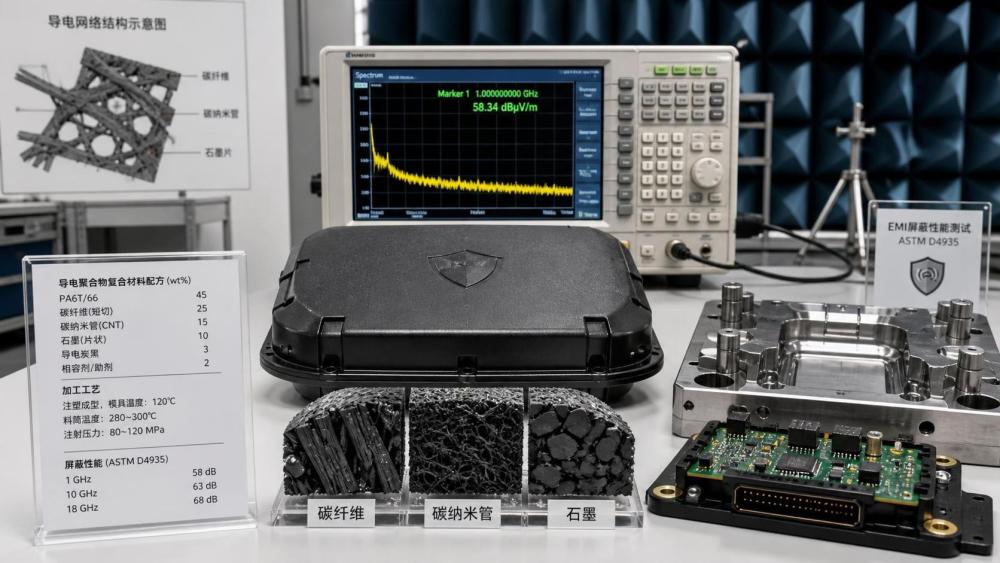
Carbon fiber raises conductivity more efficiently than spherical or near-spherical fillers because of its aspect ratio. It can improve shielding while also reinforcing the polymer mechanically. The downside is anisotropy. Fiber orientation during injection molding can create direction-dependent conductivity, which means one section of the part may shield better than another. That becomes critical in thin walls, ribs, weld lines, and around fastener points.
Carbon nanotubes (CNTs) can achieve conductivity at relatively low loading because they form networks efficiently. They are attractive when weight, retention of mechanical properties, or finer surface quality matters. But CNT-based compounds are highly sensitive to dispersion quality. Poor dispersion or damage to nanotube structure during compounding can sharply reduce the expected shielding benefit. CNT systems also tend to introduce cost and supply-chain complexity.
Graphene and graphite-based systems can support both electrical and, in some designs, thermal conductivity. Their performance depends strongly on platelet size, aspect ratio, orientation, and hybridization with other fillers. They can be useful in multifunctional designs but are not automatically superior just because the filler sounds advanced.
Metal-coated fillers or stainless steel fibers can deliver stronger conductivity and shielding, especially where higher reflection is needed. However, they may add weight, increase wear on processing equipment, affect corrosion behavior, and complicate recycling streams.
Many of the best-performing materials are not based on a single filler at all. Hybrid systems—such as carbon black plus carbon fiber, or CNT plus graphite—are often used to balance conductivity, processability, mechanical strength, surface quality, and cost. For evaluators, this means filler chemistry alone is not enough. The architecture of the filler network matters more than the ingredient list.
Percolation threshold is important, but not the full story
Much discussion around conductive compounds focuses on the percolation threshold—the point at which enough conductive filler is present to form a continuous electrical path. This is useful, but it should not be mistaken for a direct predictor of shielding success.
A compound can cross the percolation threshold and become electrically conductive, yet still fail EMI requirements because:
- the conductive network is not uniform across the molded part,
- conductivity is concentrated in one direction,
- surface conductivity differs from bulk conductivity,
- wall thickness is too low to support attenuation,
- joint leakage dominates enclosure performance, or
- the test frequency range exposes weaknesses in absorption or reflection behavior.
For this reason, bulk resistivity and surface resistivity should be treated as screening indicators, not final decision metrics. Material approval based only on conductivity numbers is a common technical mistake.
Dispersion quality often decides whether the formulation works in production
In development samples, conductive fillers may appear to perform well because the compounding process was tightly controlled at pilot scale. In volume production, the same nominal formulation can drift if feeder stability, screw design, melt temperature, shear history, or pellet quality changes.
Dispersion quality affects three things at once: conductivity consistency, shielding repeatability, and mechanical reliability. Agglomerates may create local conductive hot spots while leaving other zones under-connected. They can also weaken impact strength, reduce cosmetic quality, and create molding instability.
For technical evaluators, this is why supplier capability in compounding is as important as the datasheet. Questions worth asking include:
- How is filler dispersion monitored batch to batch?
- What compounding equipment and screw configuration are used?
- How sensitive is the material to reprocessing or residence time?
- Are conductivity and shielding values based on molded plaques, extruded sheet, or finished parts?
- What variation has been observed across production lots?
Without those answers, published EMI values may have limited predictive value.
The polymer matrix influences more than mechanical properties
Technical teams sometimes treat the base resin as secondary once the filler system is selected. In reality, the polymer matrix influences filler wetting, dispersion stability, shrinkage behavior, dimensional control, thermal resistance, chemical durability, and long-term conductivity retention.
A polypropylene-based conductive compound may be attractive for cost and weight, but it may not withstand elevated service temperatures required in under-hood automotive electronics. A polycarbonate or PC/ABS system may support good dimensional stability and enclosure aesthetics, but processing conditions and flame-retardant package compatibility must be assessed carefully. High-performance resins such as PPS, PEEK, or PEI may support demanding thermal environments, but filler interaction, viscosity, and cost can shift the feasibility equation.
Matrix selection also affects how the conductive network survives thermal cycling, vibration, humidity, and chemical exposure. If the polymer creeps, cracks, or absorbs moisture in a way that disrupts filler contact pathways, shielding performance may degrade over time even when initial tests look acceptable.
This matters particularly in applications exposed to repeated temperature swings, such as EV electronics, outdoor telecom housings, and industrial control systems.
Processing conditions can create or destroy shielding performance
Injection molding, extrusion, and compression molding do not preserve conductive networks equally. Shear can align fibers, break fragile structures, or drive filler segregation. Gate design, flow path length, wall transitions, and cooling rate all influence local conductivity.
Injection-molded parts are especially sensitive to orientation effects. Carbon fibers or platelet fillers may align along the flow direction, improving conductivity in-plane but weakening through-thickness connectivity. Since EMI leakage often exploits the weakest path, anisotropy can reduce real enclosure shielding more than expected from simple conductivity data.
Weld lines are another risk area. They may interrupt the conductive network and create electrical discontinuities exactly where structural or dimensional complexity is highest. Thin-wall sections can also reduce attenuation simply because there is less conductive path length and less material volume available for absorption.
Technical evaluation should therefore include part-representative trials, not just standard plaques. A compound that performs well in a lab coupon may fall short in a vented housing, snap-fit cover, or multi-gate geometry.
Shielding effectiveness must be read together with the test standard
EMI data can be misleading when the test method is unclear. Shielding effectiveness values depend on specimen geometry, frequency range, sample thickness, and fixture design. A reported result in dB is meaningful only when tied to the method used.
Commonly referenced methods may include ASTM D4935 for planar materials and other application-specific procedures depending on part form and end-use requirements. In some programs, MIL-related or IEC-related test frameworks may also be relevant depending on customer specification and sector. If a supplier cites “60 dB shielding,” the evaluator should ask:
- At what frequency range was this measured?
- On what sample geometry and thickness?
- Was the result average, peak, or minimum?
- Was it measured on raw material plaques or actual molded parts?
- How does the value change after aging, humidity, or thermal cycling?
Without this context, comparison across materials is unreliable.
It is also important to distinguish between compliance screening and application validation. A material may look competitive under one laboratory standard but fail in the assembled product due to seams, grounding strategy, apertures, cable interfaces, or coating interactions.
Mechanical, thermal, and EMI requirements usually conflict
There is rarely a free-performance upgrade in conductive compounds. Higher filler loading often improves conductivity and shielding, but may reduce elongation, impact resistance, surface finish, and ease of processing. Melt flow can drop, warpage can rise, and tool wear can increase. In flame-retardant systems, balancing EMI performance with UL-related electrical safety requirements may create additional formulation constraints. Specific certification requirements should be confirmed case by case, especially where customer compliance documents are mandatory.
This is why technical evaluators should avoid selecting materials based on maximum shielding alone. The better question is whether the compound delivers the required EMI margin while preserving dimensional stability, assembly performance, appearance, and manufacturing yield.
In many industrial programs, the most successful material is not the one with the highest dB number. It is the one that reaches the target reliably at acceptable thickness, cycle time, scrap rate, and long-term durability.
Common evaluation mistakes in conductive polymer compounds
Several recurring errors show up in EMI material selection projects:
- Using DC conductivity as a direct proxy for high-frequency shielding. Electrical pathways useful at low frequency do not automatically translate into strong shielding behavior across all EMI bands.
- Ignoring anisotropy. Fiber-filled systems can look strong in one test direction and weak in another.
- Evaluating only raw material plaques. Finished-part geometry often changes the result materially.
- Overlooking seam and interface leakage. In enclosure design, joints may dominate total shielding performance.
- Underestimating batch consistency risk. Complex filler systems are sensitive to compounding discipline.
- Assuming higher filler loading is always better. Processing and mechanical penalties may outweigh the EMI gain.
These mistakes are costly because they usually surface late—during validation, customer testing, or pilot production—when design flexibility is already limited.
What a robust technical evaluation should include
For material teams assessing conductive polymer compounds for EMI shielding, a practical evaluation framework should connect formulation science with production reality.
That usually means reviewing:
- target frequency range and minimum shielding requirement in dB,
- part thickness and geometry sensitivity,
- required mechanical and thermal performance,
- process route and expected filler orientation effects,
- surface resistivity and volume resistivity consistency,
- test method alignment with customer or sector requirements,
- aging behavior under humidity, heat, and thermal cycling,
- lot-to-lot consistency from the compounder, and
- assembly-level factors such as grounding, seams, fasteners, and coatings.
Where the application is critical, assembled-part EMI testing should happen early enough to avoid false confidence from flat coupon data.
Where the market is heading
The direction of development is clear: lighter and more integrated electronic systems are increasing demand for materials that combine EMI control with structural, thermal, and processing performance. This is pushing the market toward hybrid conductive systems, multifunctional compounds, and tighter cooperation between compounders, molders, and OEM design teams.
At the same time, technical scrutiny is increasing. Buyers and engineering groups are asking for more than conductivity claims. They want reproducible shielding data, stable processing windows, compliance documentation where relevant, and better evidence that performance survives real operating conditions.
That shift is healthy. Conductive polymer compounds can be highly effective EMI solutions, but only when evaluated as engineered systems rather than as commodity plastics with a conductivity number attached.
For technical decision-making, the most useful principle is simple: shielding performance comes from the interaction of filler network, polymer matrix, process history, and part design. If one of those elements is weak, the compound may still look good on paper and still disappoint in service.
Have questions about this sector analysis, or seeking best practices specific to your niche? Drop us a line below and let the senior consultants at APIM assist you.
We respect your privacy. Your information is strictly confidential.
Related News
- 00
0000-00
Do polyolefin hot melt adhesives bond well to polyethylene? - 00
0000-00
Korean Study Finds PLA Barely Degrades in Landfill After 320 Days - 00
0000-00
How to assess batch consistency from a thermal potting compounds supplier - 00
0000-00
How much weight can carbon fiber reinforced plastics save in cars? - 00
0000-00
Switching from PS to ABS Sheet Extrusion: Equipment Checks